¶ Control and configuration
The ACR-LGW device is already configured according to user requirements from the manufacturing process. Do not make configuration changes, if you are not absolutely sure, what these changes affect. It is recommended to contact the supplier or manufacturer and consult the intended issue.
The ACR-LGW can be user configured via two channels. One way of configuration is via SSH communication protocol using commands sent through the terminal application. The other way how to configure the device is via the GUI using LuCi web interface its package is installed in OpenWRT operating system.
Before attempting any of the following operations, assure the ETHERNET connection and turn on the power supply for the ACR-LGW device.
Screenshots displayed in the following sections correspond to recommended, default settings, if not specified otherwise.
For both configuration options, the user connects to the device via the ETHERNET interface, and the IP address is required.
¶ IP Address Discovery
The IP address of the particular device can be found on the box label. IP address looks for example like this number code “192.168.20.148”.
If the IP address is unknown, follow next steps:
- Interconnect the ACR-LGW via the USB cable. Use the console USB port (miniUSB connector) on the ACR-LGW side.
- Run the terminal application on the computer.
- Navigate to the /dev directory using the command
cd /dev - Display the list of devices connected to the computer their names start with tty using the command
ls -d tty*

- Find the device named ttyUSBx, where x is the order number, e. g. “ttyUSB0” from the example above
- Connect to the device using the command (115200 Baud is the default data rate)
screen /dev/ttyUSB0 115200 - Hit the enter key and the welcome screen of the OpenWRT operating system is displayed on the screen. The command line on OpenWRT operating system is ready.

- To discover the IP address of the ACR-LGW device, type the command
ip a
The IP address of the wired ETHERNET connection can be found in the list on the screen. Look for the “eth0” entry.

¶ SSH access
The device running on the OpenWRT always listens for SSH commands on the port 22. To connect via the SSH, type the command ssh root@xxx.xxx.xxx.xxx
Where xxx.xxx.xxx.xxx is the discovered ACR-LGW IP address, example “192.168.20.148”.
To control and configure the ACR-LGW device via SSH connection, visit OpenWRT web page and follow their User Guide.
To close the SSH session, use the command exit
¶ Operating system
The OpenWRT operating system is running on single board computer and is responsible for controlling entire ACR-LGW unit. OpenWRT is installed on flash memory and contains modifications prepared for ACR-LGW hardware.
¶ Installation
Newest and stable version is always installed on the new device and all necessary settings are done during the manufacturing process to fulfill customer requirements.
If necessary, the procedure for the OpenWRT operating system installation can be found here. Whole procedure is not simple and requires advanced skills. Correct source code for particular hardware needs to be selected and built. Please contact the supplier/manufacturer to discuss the operating system installation.
¶ Update via LuCi web interface
The procedure describing update of operating system from LuCi web interface can be found in documentation here.
The correct source file containing operating system is required for installation. Procedure is not simple and requires some skills. Please contact the manufacturer/supplier to discuss the update options.
¶ Update via SSH
Another method for operating system update uses SSH via ETHERNET connection and transfers source image to ACR-LGW device. Update is run directly from ACR-LGW device.
Contact the supplier/manufacturer to obtain the correct and fresh source image with the operating system.
To perform operating system update from USB memory device, continue with following instructions:
- Discover the IP address of the ACR-LGW device.
- Find folder containing the system update image and open folder in console. Source file name is for example omega2.bin. Verify the file is located in folder using command
ls - Source image file needs to be SSH transferred to the root folder of ACR-LGW device. Use the command
scp omega2.bin root@IPaddress:/root
Fill in the discovered IP address instead of IPaddress field. For example:scp omega2.bin root@192.168.20.12:/root
Confirm authentication dialog writing yes, if requested. Type password onioneer to start the transfer. Transfer takes about a minute and it's progress is shown in console.

- Connect to the ACR-LGW device via USB serial console using command
screen /dev/ttyUSB0 115200 - Go to the root folder
cd root
By using command ls verify that transferred system image omega2.bin is located in folder ( root/ folder may contain image file only, but more other files can also be presented).
- To start the system update, run command
sysupgrade omega2.bin - Wait about 5 minutes to finish update process. ACR-LGW device reboots automatically. After pressing Enter key, text root@AcriosGW:/# is displayed in the console.
- System update is finished.
- After each restart, ACRIOS GW logo is shown in the console.

¶ Update from the USB memory device
New version of operating system can be also installed using USB flash drive. This method is especially useful, when ACR-LGW device update is not possible using previous methods.
To perform OS update, follow these steps:
- Rename image received from the supplier/manufacturer to omega2.bin and copy it to a flash drive (root of the device)
- Power off the ACR-LGW device by disconnecting power supply (or PoE injector)
- Connect the USB cable to serial console port (miniUSB)
- Connect the flash drive to USB port
- Hold SW Reset button and power on the ACR-LGW device until boot menu appears in console
- Type “2” to select the Flash firmware from USB storage
- Firmware upgrade process will start (it can take up to 5-10 min), after the update finishes, device reboots automatically
¶ LuCi web interface
The LuCi web interface allows you to easily manage and configure ACR-LGW device settings.
If LuCi web interface package is not installed, install it using this guide.
To connect to the ACR-LGW device through LuCi web interface, type device’s IP address to web browser. Login page is displayed. Type Username and Password delivered together with the ACR-LGW unit. If login credentials are unknown, contact the supplier or manufacturer.

After the successful login, the Status of the system is displayed.

Main menu is located at the top of LuCi web page and gives user access to system diagnostics and individual system settings.
Following sections describes the most important menu entries and explains settings and options. Menu entries that aren't mentioned here are described here.
¶ LoRa menu
This menu allows you to configure LoRa wireless connectivity.

From the Region combo box, the LoRa region can be selected. EU, US and CN options are available. Depending on selected region, the ACR-LGW device is automatically configured to work with a frequency plan predefined for particular region. Basic overview of channel assignment is summarized in following table. CN option is not available with current hardware setup.
| LuCi designation | LoRaWAN standard | Frequency range | Center frequency | Available bands |
|---|---|---|---|---|
| EU | EU863-870 | 863 – 870 MHz | 868 MHz | 8 |
| US | US902-928 | 902 – 928 MHz | 915 MHz | 10 |
Network server settings section serves for network configuration of the gateway.
IP address describes the address to which all nodes connect. - THIS IS CRUCIAL - by default it's set to 127.0.0.1 or ns.acrios.com
Uplink and Downlink port can be the same, because half-duplex form of communication is used.
Gateway ID field allows you to distinguish your gateway from others and create LoRaWAN network. If only one gateway is connected to the network, Gateway ID parameter is not important.
To save all changes click on Submit… button and restart the ACR-LGW device (go to System menu and select the Reboot item). Login is required after reboot.
All LoRaWAN related settings are stored in /etc/lora/global_conf.json and can be also modified manually using serial interface or SSH if needed.
¶ Connections
The ACR-LGW PCB is assembled with almost all components from the bottom side. Top side contains interfaces and connectors to make installation and connections easier and without need to completely remove PCB from the box.
The PCB layout is universal, some connectors might not be assembled, depending on your hardware configuration.
Next figure represents full functionality of the ACR-LGW. Not assembled connectors and components are used for debugging purposes or will serve for future functionalities.
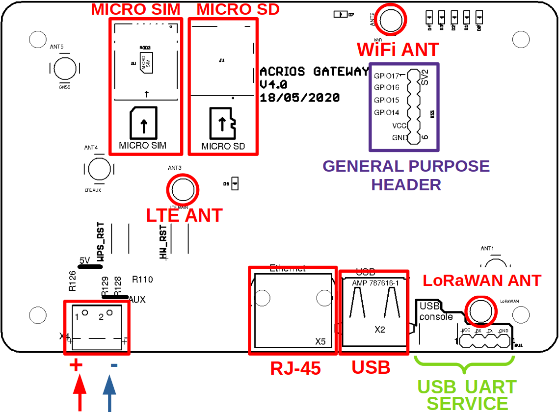

All antennas are connected via MCX connectors. To disconnect antenna, gently pull the connector until it releases. To connect antenna, gently push the connector towards the PCB until it clicks.
The power supply is connected via screw terminals. Properly tight screws in terminals to avoid transition resistance and possible supply cuts.
¶ LTE Connection
In order to connect the ACR-LGW to internet via LTE, please follow these instructions:
- Disconnect the device from power
- Insert the SIM card (micro sim format) in to the micro SIM slot
- Power on the device
- Make sure the LAN cable is connected and the device is accessible from your PC.
- Open the LuCI configuration interface. If you don't know how to do this, please follow the LGW Quick Start Guide.
- Open the “Interfaces” config page (Network → Interfaces)
- Select “Add new Interface”, name it “LTE” and select “QMI Cellular” protocol
- In the following dialog, enter parameters provided by your LTE provider
- Click “Save and apply” to apply the settings.
- The interface should come up within a minute or two
¶ Service connectors
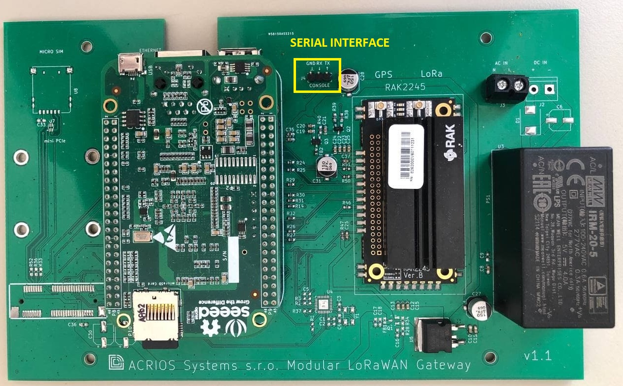
For service operations, settings and control, two console service connectors can be used. Default rate is 115200 Bauds.
The UART serial interface uses RX and TX signals only. Voltage levels are referenced to 3.3 V DC. The second console interface is converted from UART to USB and guided out to miniUSB connector.
¶ Modular LGW (MLGW)
In case of MLGW, use USB to UART TTL cable to connect to serial interface.
¶ How to insert SIM card to MLGW
1. Unplug LTE antenna by hand and remove two screws with screwdriver, which are holding the LTE module
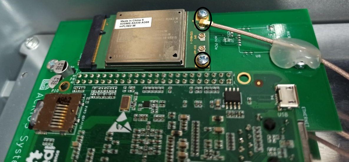
2. Take out the module and turn it upside down. There you can see a SIM card slot.
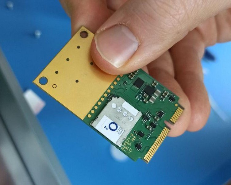
3. Insert the SIM card into the slot and mount the module back. First screw in the screws and then plug the antenna back.
¶ How to use with custom APN
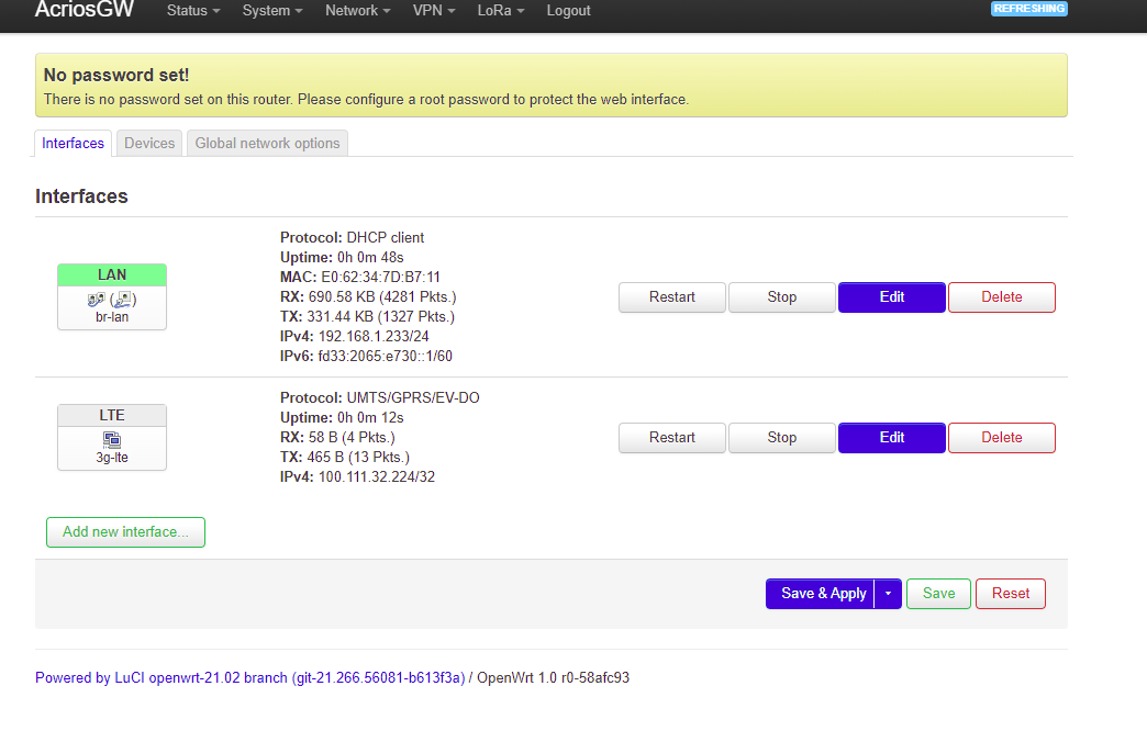
1. Setup custom APN in LuCI interface
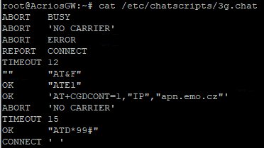
2. In file /etc/chatscripts/3g.chat, edit line with AT+CGDCONT (for example with nano /etc/chatscripts/3g.chat)
3. Reboot, wait several minutes, you can check APN with: comgt -d /dev/ttyACM2 info &
4. Try to reboot again, if the module does not change its APN on the first time.
5. Now you should have custom APN, you can check you have IP from a private IP pool using: ifconfig 3g-lte
¶ General purpose header (GPIO)
User can utilize four digital general purpose input/output ports directly connected to the core module. Also the 3.3 V DC voltage is accessible through pin header SV2, that is assembled based on user requirements.
- if the port is configured as output, it is referenced to 3.3 V DC
- if the port is configured as input, the maximum allowed applied voltage level is 3.3 V DC.
These general purpose input/output ports can be utilized to sense or control another hardware unit assembled together with the ACR-LGW device inside metallic box.
All interfaces are equipped with ESD protection devices. Used components secure sufficient level of isolation between an external power supply and internal electronics.